


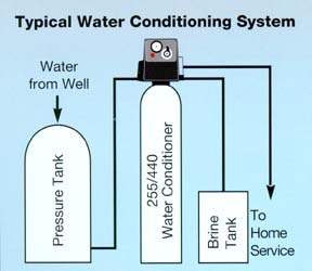
GENERAL WATER SOFTENER INSTALLATION
Notice: This is only a general instruction reference. Be sure to read your owners manual for any special instructions on your particular softener. The customer is responsible for following any state and/or local regulations and plumbing codes pertinent to the purchase, installation, and operation of our products. Aplus Water LLC always recommends that you have a licensed plumber install your water softener.
Step 1
The location of your softener is important. It should be in a protected dry, level, and non-freezing area (34-120 degrees F).
The 2 tanks should be set close to each other. The square tank is your salt (brine) tank (for softener salt or potassium chloride). This is the tank that you will have to refill sometimes, so make it the more accessible of the 2 tanks.
Do not put salt in this tank until you have put the softener into service and have tested the cycles.
Step 2
You will need a standard outlet that is not controlled by a switch.
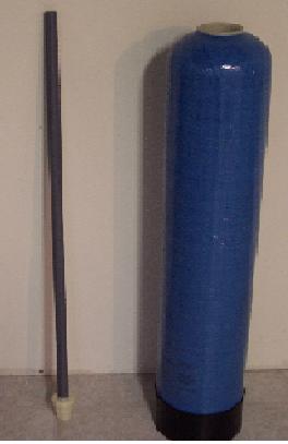
The distributor tube is on the left and should be placed in the middle bottom of the resin tank with the white end down — BEFORE ADDING THE RESIN!
Note: If your softener shipped loaded, skip ahead to Step 4.
(If your softener weighs more than 10lbs, it shipped loaded)
Step 3
Place the resin tank where you want to connect it to your water line, because it will be hard to move after the resin is added.
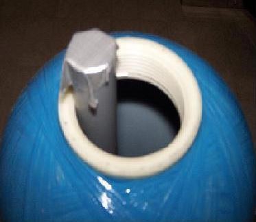
Place the distributor tube into the bottom middle of the resin tank.
Place a peace of tape over the open end of the distributor tube to keep any resin from falling into the distributor while pouring it into the mineral tank (unless a plug is already in place).
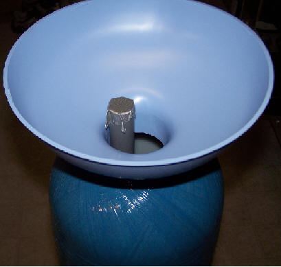
Place the funnel (provided) into the mineral tank, and begin to pour or scoop the resin into the mineral tank.
Be careful to keep the distributor tube centered as best you can, while filling. An easy (but slower) way to fill the mineral tank is to take a small scoop and pour the media into the funnel. The media beads tend to stick to the funnel so by filling slowly the media will go into the tank easier.
Note: If you have been shipped more then one bag of resin, the resin is the same in each bag. So, you may pour it in any order.
Once the filling of the mineral tank is completed, carefully remove the tape or plug from the distributor tube. Do not pull upwards on the distributor tube.
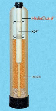
FOR PEOPLE WITH THE KDF MEDIA GUARD FOLLOW THESE ADDITIONAL DIRECTIONS.
| Attach the KDF Media Compartment to the control valve — align the slots and turn until it locks in place.
The control valve (head) now must be installed onto the mineral tank. Be sure the large 0-ring is in place. Slip the control unit and KDF Media-Guard canister onto the distributor tube. Then carefully screw the valve onto the tank–NO pipe dope should be used on the threads. The control valve should be hand tightened, snugly, clockwise |
Step 4
The control valve (head) now must be screwed onto the mineral tank. Be sure the large O-ring is in place and lubricated (you can use standard cooking oil to lubricate, if necessary).
As you start to screw the control valve onto the tank, make sure the hole in the center of the control valve fits over the distributor tube.
Note: DO NOT USE pipe dope or tape on the threads! The control valve should be hand tightened, snugly, clockwise. DO NOT OVER TIGHTEN VALVE!
Step 5
You are now ready to install the bypass valve to the control valve. Be sure to lubricate o-rings with cooking oil before installing.
Note: DO NOT OVER-TIGHTEN THE SCREWS! Doing so will cause a leak! Just hand-tighten snugly, and that is all that is needed.
Step 6
Turn off main water valve. Water connections to and from softener should now be connected.
Note: Be sure to Attach the inlet to the bypass with the arrow pointing in and the outlet to the arrow pointing out.
Step 7
You will need a drain for the backwashing cycles. The drain should be no further than 20 feet from the softener.
You will need to purchase this flexible 1/2 i.d. plastic pipe (can also be vinyl, polyethylene, polybutylene, etc) and a small clamp to hold the tubing over the fitting. The same size plastic pipe will be used in Step 8.
This backwashing drain line will be under pressure when the backwash cycle is working, so make sure the drain line is secured.
The drain line will need to drain into a drain, which should be a minimum of 1 1/2” size, and ideally be below the top of the head of your softener. Local codes should be adhered to.
Do not connect the drain line directly into a drain. Allow an air-gap between the drain line and waste line to prevent possibility of back-siphon.
Be sure to use teflon tape on this step.
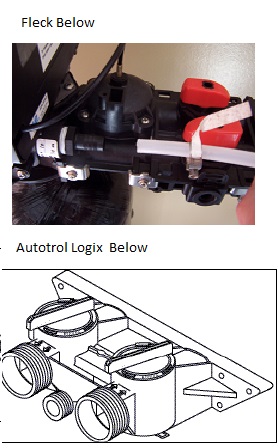
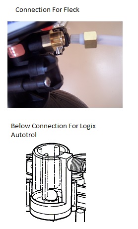
Now you will connect the drain line.
For the logix the middle connection is where you will connect this drain line.
Step 8
Between the valve and the salt tank you will need to connect the furnished 3/8” O.D. tubing to the controller with compression nut and safety float with the push fitting.
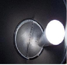
Take the cap off the white tube inside the salt tank pictured below.
Note: If overflow is not installed already, now is the time to do it, because it holds the brine well to the salt tank.
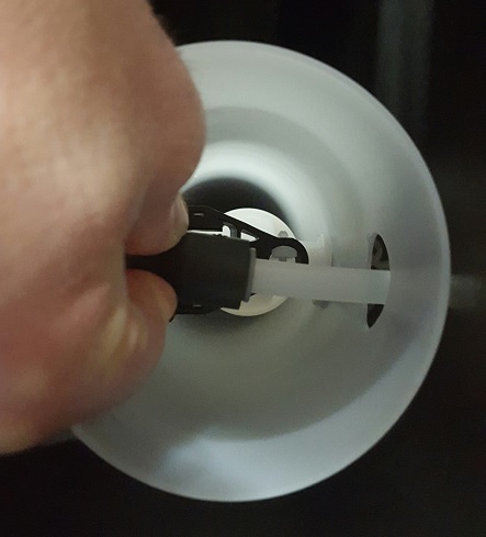
Connect the 3/8 inch tubing by pushing it into the quick connect elbow in the brine tank.
You will be attaching the other end of the tubing and nut to the smaller of the two threaded drains on the controller.
Step 9
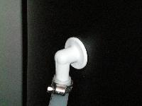
Salt tank overflow (this is the elbow on the side of your salt tank). Attach 1/2″ i.d. plastic tubing to the fitting from the salt tank and run to a drain.
This drain line will not be under pressure. DO NOT tie into the backwash drain line! This line should be higher than your drain line.
Overflow drain line must be a separate line from fitting to the floor-drain, sewer, tub, etc.
INITIAL POWER UP
1.Add water to the salt tank. With a bucket or hose, add approximately 1 to 2 gallons of water to the salt tank.
2.Set your bypass in bypass mode and slowly turn on the main water valve to your home until all pipes are pressurized. Now open the bypass valve SLOWLY. You do not want to be surprised by leaks. Let the resin tank fill completely, then open the bypass valves the rest of the way.
WARNING: If opened too rapidly or too far, media may be lost out of the tank into the valve or the plumbing. In the 1/4 open position, you should hear air slowly escaping from the valve drain line.
- Plug the power supply transformer into a socket that is not controlled by a switch or timer.
4.Program your water softener. Set the time of day, gallons between regeneration or days between regeneration. Reference your owner’s manual for your particular water softener settings and programming.
FOR FLECK SXT ELECTRONIC DIGITAL WATER SOFTENERS CLICK ON LINK BELOW FOR PROGRAMMING.
NOTE: ONLY CHANGE HARDNESS AND CAPACITY. CAPACITY IS HOW MANY GRAINS WATER SOFTENER YOU HAVE SO IF YOU HAVE A 64,000 GRAIN WATER SOFTENER SET C TO 64.
MOST SETTINGS SHOULD STAY IN THE DEFAULT SETTINGS!
5.Once your softener is programmed advance your controller to manual regeneration. The regeneration process is a 1 to 2 hour process.
6.Check for any leaks during this initial regeneration. Also make sure that there is water in the salt tank after the regeneration is complete.
7.Your softener is now in operation and you can add salt.
Note: Be sure to always have at least one bag of salt in the brine tank at all times. You may fill the salt tank all the way up if you like. Standard water softener salt works well.
SPECIAL NOTE FOR METERED UNITS: BE SURE THE METER CABLE IN THE BACK OF THE VALVE IS PLUGGED INTO THE METER.